Page 5 of 6
Posted: Thu Nov 08, 2007 10:58 am
by The Benz Master
grippo wrote:Let us know if the old ms2 processor gives a different result than the new one.
As far as the extra pulses, this may be a result of the drastic change in rpm from intake to compression strokes... That would be fine except your cranking rpm is only 100, so it will immediately go to after start and possibly to normal running very quickly, depending on conditions.
Yes, this is exactly what i tought but i did'nt think about the low cranking RPM (which is needed to get spark timing right). I'll try this tonight.
We're getting somewhere, finally

thanks Grippo
Posted: Thu Nov 08, 2007 9:57 pm
by The Benz Master
ok, i first set the cranking RPM to 95 too... this yielded PERFECT TIMING AND SPARK OUTPUT !!

But.... when i try to start the engine with fuel and all, it does'n work... as soon as it fires 2 or 3 times, i t cuts off and it seem sthat MS gets some lag... because in my datalog, after fiering 2 or 3 times, ms keeps all the last running data and ignores what is realy going on for a little over 2 seconds and then trys to start again.
not sure if it's juste the next pulse tollerance that takes a beat when first explosion occures or if it's something else. I tried upping the tollerance to 125% for all of them without sucess... i'll try 400% next... it will take this part of code out of the question. I also noticed the injector led stoped blinking as soon as the engine died even if i continuad cranking and when it started to blink again, the engine restarted again doing the same thing over and over...)
will try my old processor after 400% pulse tollerance...
Posted: Fri Nov 09, 2007 3:36 pm
by grippo
Based on your datalog and checking through the code, what appears to be happening is the first few ignition pulses are detected and spark is fired. Then all input pulses stop - or are not detected by the processor, and the rpm, pw and other engine variables freeze, but sensor data is still processed.. Then there is a wait of about 2.4 seconds, then rpm goes to 0 and there is a resynch as input pulses are again detected. The 2.4 seconds comes about because the processor latches the time at the start of each detected tach pulse. Then in the main loop it checks the clock and if clock time - latched tach time (in tics of .128 ms) exceeds 18750/ no cyl (= 50 rpm) then lost synch is declared, rpm and engine are set to 0, and the processor waits for a new tach pulse. Normally I work with 4 or 8 cylinder setups and the resynch occurs in a fraction of a second, but with 1 cylinder it nominally takes 2 revs per tach pulse and at 60 rpm this is 2 sec; at 50 rpm it is 2.4 sec. I know that you are running 1 cyl wasted so it should be 1.2 sec between tach pulses - but it doesn't matter. This is just a rough test to determine if the engine is stalled. If there had been any actual input tach pulse detected, a new time would have been lateched and the processor would have kept firing. But no pulse was detected. This detection is not in the software - it is built into the processor to detect pulses and interrupt the code. The code then calculates dt3, the difference between the time the last tach pulse was detected and the present time. There is very little that can go wrong here - I believe the processor simply stopped detecting tach pulse inputs. If you can duplicate this test, I would like to see you scope the tach input at the processor - so you get a nice square wave. Then watch the MT rpm - when it freezes for 2 seconds do the square waves stop ? You can't scope the VR sensor because that is not what the processor detects. It has to have a nice square wave because in the mode used it ids looking for an edge.
Posted: Sat Nov 10, 2007 9:45 am
by The Benz Master
already done.. just had to repair my usb wire for the camera !! there is some kind of dip in the irq when engine fires but it's still there.
I have my MSD driving a twin tower GM coil with both plugs in the cylinder....at 11.5:1 C.R.... but still... it fires fine when engine is not running... is current requirement so diferent when engine runs?
VR sensor on top, IRQ on bottom. I've also routed a wire outside the Box for IRQ probing when i installed the dipswitch... much easyer than probing on processor pin directly

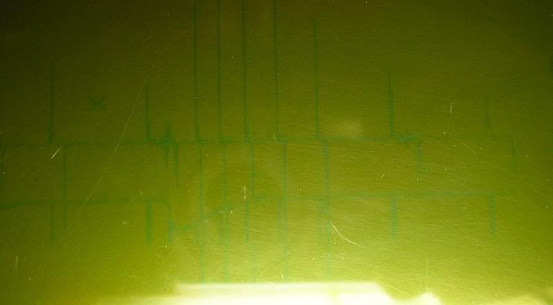
P.S. picture not really clear, please tell me if you need a beter one.
Posted: Sun Nov 11, 2007 9:36 am
by grippo
The picture is hard to read and to see if the IRQ pulses show any noise within the square wave. More importantly, I would prefer the top picture to be the spark output signal from the processor, so there are two sets of square waves. Then if this shows a square wave IRQ without an ignition output above it, I would like to relate this time to what is going on in the datalog. If you can't get a picture, you can draw it out by hand or describe in words.
What I am getting at is that as far as I can see it would be impossible to have the processor ignore an IRQ pulse. It will either put out a spark pulse or it will lose synch and try to regain synch, in which case the deltaT column at the end will change. This represents the time in microsec between IRQs and I have never seen it fail to change when there are two successive IRQs. If you think this is what is going on, then I will send you special test code to verify this. Also, you should be able to look at the IRQ pulses and measure the times between detections (make sure whether it is detecting falling or rising edges). These times should match what is in the delatT column of the datalog.
Posted: Wed Nov 14, 2007 5:58 pm
by The Benz Master
Tham, my GF went away with my digi camera so i have to take the webcam to show the graph... not really beter qualitu pic but... here it is.
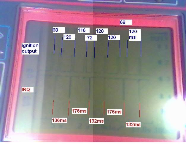
Today i get those silly "twin sparks" even at cranking... with trigger to so i tought about it and i changed the battery i use for a larger one, cranking speed is a bit up compared to the other day... not sure if it can be related.
this is at cranking speed with next pulse tollerance set at 250 for all 3...
matching datalog
P.S. thanks Jim for the input, i'll look into this later. If i can at least get a correct signal to the ignition for now... i'd love to see the coil burst into flames as i wind the motor !!

Seriously, i've been lurking the idea of plugging 2 coils on plug from a CBR or something like this... but i'll see when i get there... just need to find some short ones.
Posted: Thu Nov 15, 2007 9:58 am
by grippo
This is really good data - thank you for getting it. I will analyze it tonight with the datalog. My only question is what did you set for the cranking speed ?
Posted: Thu Nov 15, 2007 11:16 am
by The Benz Master
50 RPM = max cranking speed
i think we are chassing more than one problem... this is why we have so much trouble figuring it out.
thanks grippo
Posted: Thu Nov 15, 2007 7:25 pm
by grippo
I have a new program(attached) for you to test if you can. This program removes all but one test for missing/ extra pulses and if there are any it will immediately set rpm to 0 and we will know from the data log. This test may tell us something about the extra outputs. If they disappear i will know what caused them. Please leave all the inputs exactly as you did in the last picture/ datalog.
I agree that there are two problems here. The other is what is going on during the 2.4 secs when it is not detecting anything and the rpm stays frozen. When this happens are there still IRQ pulses coming in, but no ignition pulses going out ?
If that is the case I will try to duplicate the erratic IRQ timing you are seeing - with short delta_ t on one revolution(compression) and longer on the next (exhaust).
Posted: Thu Nov 15, 2007 7:28 pm
by grippo
Sorry - forgot the attachment. Here it is.
Posted: Thu Nov 15, 2007 10:35 pm
by The Benz Master
grippo wrote:
I agree that there are two problems here. The other is what is going on during the 2.4 secs when it is not detecting anything and the rpm stays frozen. When this happens are there still IRQ pulses coming in, but no ignition pulses going out ?
yes, exactly, the irq is still there (but it has some kind of dip in it) and no more spark.
here is what the dip looks like...
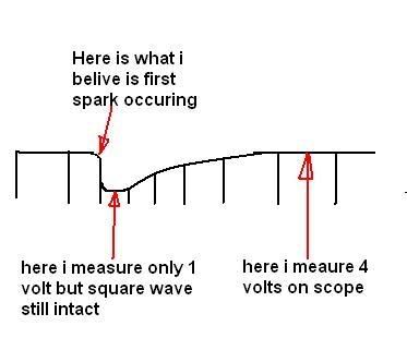
This is what the not clear picture of scope a few posts above was suposed to show. i still have it saved in the scope if you need timing of each signal.
Posted: Fri Nov 16, 2007 5:13 pm
by grippo
If the signal dips to 1 volt then it will not be seen by the processor. It may dip after a spark because the spark is causing the voltage to drop. Try putting a 1 farad audio capacitor acroos the battery terminals - this will keep the voltage up - it needs to be over at least 2.5 Volts to be seen by the processor.
That said, I don't see any dipping in the scope shot above - everything seems to be at the same level. Also, in your last sketch it appears that the dip only lasts for < 1 second, but there is no tach detection in the datalog for 2.4 sec, at which point the processor declares lost synch. Had a tach signal come in earlier, the processor would either have sparked or declared lost synch/ rpm=0 immediately because the timing was off so much.
Posted: Fri Nov 16, 2007 6:05 pm
by The Benz Master
No, not the one directly above, the second one....
And i already have a 1.5 farad capacitor on the battery.
the voltage is under 2.6v for only 76ms and total lenght about 180 ms
Posted: Tue Nov 27, 2007 5:53 pm
by The Benz Master
" If they disappear i will know what caused them. Please leave all the inputs exactly as you did in the last picture/ datalog."
I still get the same output as the scope above and datalog keept recording RPM...
 "I agree that there are two problems here. The other is what is going on during the 2.4 secs when it is not detecting anything and the rpm stays frozen. When this happens are there still IRQ pulses coming in, but no ignition pulses going out ?"
It depends... it mostly does it when i let off the starter button, it keeps fiering without any input. When i tried to start the engine, when engine died, data froze , wether it was still cranking or not and i was just getting 0rpm and no sparks. Yes, IRQ is always there eccept the 1v dip for +- 80ms at the time of the first spark.
still very confusing
Posted: Wed Nov 28, 2007 6:43 am
by grippo
I was able to reprogram my tach pulse generator so that it put out tach pulses with something like 170 and then 220 ms between them and keeps repeating this sequence. They also stay high for most of the time, then a very short(~10 ms) dip to ground - just like your. This caused very similar behavior to what you have seen - the output timing is very bad, extra outputs, loss of synch, etc.
However, I don't trust the output of my function generator, and this problem of crazy outputs could take a while to debug. I will get to it eventually, but right now I am in the middle of testing the sequencer board and Bruce has ordered me to continue until this is done because we need to know the hardware works before we go into production.
Posted: Wed Nov 28, 2007 10:31 am
by The Benz Master
in this case, is there a way to get a normal square wave output from the VR circuitry? with some mods if needed? that would generate a square wave the same lenght than my trigger instead on only detecting 60* BTDC?
i know some electronics but i'm not into it deep enough to design my own VR to square wave circuit

thanks
Posted: Thu Nov 29, 2007 10:24 am
by grippo
The circuitry in the schematic for the V3 board that takes the VR input and converts it to a square wave for the tach input to the processor does exactly this, and you could duplicate this circuit by itself and then add in the circuitry from the processor output to the output from the coil driver circuit and the motor would drive itself. However, you would end up with fixed timing. You would be better off with a distributor.
Posted: Thu Nov 29, 2007 4:58 pm
by The Benz Master
grippo wrote:The circuitry in the schematic for the V3 board that takes the VR input and converts it to a square wave for the tach input to the processor does exactly this, and you could duplicate this circuit by itself and then add in the circuitry from the processor output to the output from the coil driver circuit and the motor would drive itself. However, you would end up with fixed timing. You would be better off with a distributor.
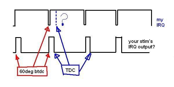
Ehhhh... i think you miss understood what i meant...
my thing here is giving me a IRQ signal that looks like the one on top and you're telling me that it's problematic that with the IRQ at the bottom (like it should be it will work ok... i just want to know how to make it like it should and everything will work fine!?
Posted: Sat Dec 01, 2007 7:54 am
by grippo
If you just inverted it with a transistor and then changed the IRQ polarity in your input msq, that would give you something closer to the bottom with the same timing. But this is probably the same as reversing polarity on the VR sensor. But I really don't think this is the problem - I just mentioned it, but as I think about it, the short part of the IRQ is about 10 ms - this is a very long time - you might have a problem at 10000 rpm, where it would be only about .5 ms, but not at cranking rpm.
Posted: Sat Dec 01, 2007 5:54 pm
by The Benz Master
well, the engine will only reeve at 8000 rpm MAX but it still makes it about .63 ms, whis is not verry high.
Tried inverting the VR sensor wires today.. it seems to miss a lot of pulses from the irq and timing not at it's place at all.. but i just did a quick try, did'nt even compare to vr sensor output... will investigate more on this on tuesday.