Need Help with my intake design
Posted: Mon Sep 21, 2009 9:03 am
Hello all,
I've got a bit of a dilema with my intake design, and I'm finding this out after I have already designed and had most of the fabrication finished. The design is for a hot Mopar 360 and uses a tunnel ram base as the foundation. I am basically at the point of welding it up but I need to work out a couple more details before I finish it. Here's a pic of the intake (throttle body adapter not shown in the image):
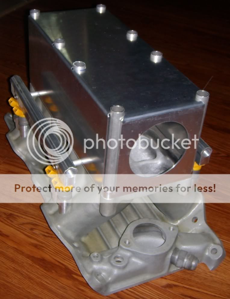
As you can see it has plenty of plenum volume already, which brings me to my first "problem". Should I attach the throttle body to the front opening (the circular cut out at the front of the intake) or should I attach it to the end of the cold air tube? The reason I ask this is because I am interested in trying to mitigate the effects of the turbulent air flow behind the throttle butterfly by giving the airflow some time to become more developed. The problem with this is that the intake tube will in effect become an extension of my plenum and increase the already large plenum from about 450 cu in to about 590 cu inches (this is assuming a 20" intake tube length, I'm not sure on the exact length yet, but I'd like to feed the tube to an outlet box in my fenderwell). Do any of you guys think I should keep the throttle body at the entrance to the plenum or do you think it might be worth it to place the TB at the end of the tube?
The second problem I have is that the welder told me he can't weld in my injector bungs because of the tight angle of the bungs in relation to the outer walls of the ports. You can see this here:

I took a look at the bungs, and it appears that if I cut off the large bulge at the top of the bung that I would gain a great deal of clearance for welding. As far as sealing goes it doesn't appear that it would affect anything, as the o-ring interface is below this bulge. At that point it would look more like the setup pictured here:
http://www.rossmachineracing.com/images ... slarge.jpg
Any ideas? I appreciate any help I can get here guys.
I've got a bit of a dilema with my intake design, and I'm finding this out after I have already designed and had most of the fabrication finished. The design is for a hot Mopar 360 and uses a tunnel ram base as the foundation. I am basically at the point of welding it up but I need to work out a couple more details before I finish it. Here's a pic of the intake (throttle body adapter not shown in the image):
As you can see it has plenty of plenum volume already, which brings me to my first "problem". Should I attach the throttle body to the front opening (the circular cut out at the front of the intake) or should I attach it to the end of the cold air tube? The reason I ask this is because I am interested in trying to mitigate the effects of the turbulent air flow behind the throttle butterfly by giving the airflow some time to become more developed. The problem with this is that the intake tube will in effect become an extension of my plenum and increase the already large plenum from about 450 cu in to about 590 cu inches (this is assuming a 20" intake tube length, I'm not sure on the exact length yet, but I'd like to feed the tube to an outlet box in my fenderwell). Do any of you guys think I should keep the throttle body at the entrance to the plenum or do you think it might be worth it to place the TB at the end of the tube?
The second problem I have is that the welder told me he can't weld in my injector bungs because of the tight angle of the bungs in relation to the outer walls of the ports. You can see this here:
I took a look at the bungs, and it appears that if I cut off the large bulge at the top of the bung that I would gain a great deal of clearance for welding. As far as sealing goes it doesn't appear that it would affect anything, as the o-ring interface is below this bulge. At that point it would look more like the setup pictured here:
http://www.rossmachineracing.com/images ... slarge.jpg
Any ideas? I appreciate any help I can get here guys.
