Hello Toyota guys,
I've got 4 of those Toyota COPs, the mechanic was not sure if/what was the reason that the had to be replaced, do you know something about pin order (4 pins)? There are no numbers to see.
I checked www for pics but couldn't find, hope my description is clear enough.
The very young mechnic told me that those devices s/could be able sense ion current. Is this a rumour?
Thanks
»Horst
Edit: Maybe this Ignition signal from ECU Toyota RAV 2.0 1995 http://www.picotech.com/auto/waveforms/graphics/p22.gif .
Toyota COP 90919-02243 (RAV?) pin order required
-
ami8break
- MegaSquirt Newbie
- Posts: 13
- Joined: Sun May 02, 2004 10:45 pm
- Location: Austria, Graz
- Contact:
Toyota COP 90919-02243 (RAV?) pin order required
MS1 V2.2 MSnSExtra 025x1 'EDIS' MT2.25b627, flat twin, MPI, dual ego feedback
_________________
DIY CDI project http://www.molla.org/DIY-CDI
_________________
DIY CDI project http://www.molla.org/DIY-CDI
-
Scott
- Running MegaSquirt
- Posts: 10
- Joined: Sat Apr 03, 2004 10:38 am
- Location: Colorado Springs, CO / USA
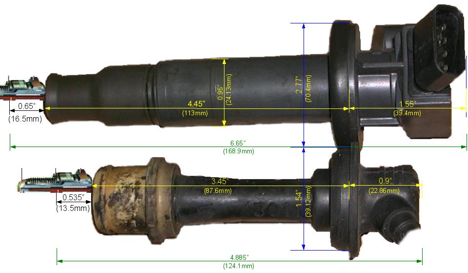
I have a set of the Toyota coil packs from a 2000 Celica GT 1.8L. They look like:
http://planetcampbell.us/CoilPackDimensions.jpg
I haven't made them do anything yet, but my notes say the pinout is: [1 2 3 4 )
Where:
1 = Switched battery voltage
2 = IGF (signal from coil to ECU to verify spark occurred)
3 = IGT (signal to coil from ECU, spark on falling edge, +5V logic level)
4 = Ground
No guarantees on the data.
Success Story here: viewtopic.php?t=685
http://better-browser.com/
Boycott Sony, here's why: http://blogs.washingtonpost.com/securit ... _hack.html
http://better-browser.com/
Boycott Sony, here's why: http://blogs.washingtonpost.com/securit ... _hack.html
-
ami8break
- MegaSquirt Newbie
- Posts: 13
- Joined: Sun May 02, 2004 10:45 pm
- Location: Austria, Graz
- Contact:
Hello Scott,
thank you very much! My COPs look very similar your upper COP (picture).
Geometry is slightly different. Diameter at anti vibration rubber is 40-45mm, coil Ø ~23m, long lenght is ~122mm, short one is ~30mm, distance to plug surface is ~17mm.
Best of all, socket is the same. Unfortunality no marks are visible, just a 'nose' on the upper side to prevent plug from disconnecting. Let's say nose is defined on upper side and I call pins (left beginning) A, B, C, D.
i....infinity >20MOhm
Unfortunality no marks are visible, just a 'nose' on the upper side to prevent plug from disconnecting. Let's say nose is defined on upper side and I call pins (left beginning) A, B, C, D.
i....infinity >20MOhm
My new cheap DMM shows different resistance at different (high Ohm) ranges, maybe an effect of ignition electronic.
Do you can estimate which order pin1234 vs pinABCD is? The infinity of pinC could indicate - but what? And diodes could cause differrent resistances at different DMM polarity.
»Horst
thank you very much! My COPs look very similar your upper COP (picture).
Geometry is slightly different. Diameter at anti vibration rubber is 40-45mm, coil Ø ~23m, long lenght is ~122mm, short one is ~30mm, distance to plug surface is ~17mm.
Best of all, socket is the same.
Code: Select all
.
red       A          B          C          D            HV
black
A         -         390         i          16k        72k
B        390        -           i       16k-28k       73k
C        35k        36k         -          71k      70k-148k
D        25k        25k         i           -        14k   38k
HV i i i i -My new cheap DMM shows different resistance at different (high Ohm) ranges, maybe an effect of ignition electronic.
Do you can estimate which order pin1234 vs pinABCD is? The infinity of pinC could indicate - but what?
»Horst
MS1 V2.2 MSnSExtra 025x1 'EDIS' MT2.25b627, flat twin, MPI, dual ego feedback
_________________
DIY CDI project http://www.molla.org/DIY-CDI
_________________
DIY CDI project http://www.molla.org/DIY-CDI
-
Scott
- Running MegaSquirt
- Posts: 10
- Joined: Sat Apr 03, 2004 10:38 am
- Location: Colorado Springs, CO / USA
The Toyota convention is shown here:
(Toyota seems to be "gender-confused" because gender applies to the pins not the housing, but they are calling the male side female)
So, looking into the pins with the tab up, I number the pins from left to right. I did a few quick restance measurements and, using my numbering scheme, this is what I found:
1 to 2 = 345 Ohms
1 to 3 = i
1 to 4 = 3.8k Ohms
2 to 3 = i
2 to 4 = 4.18k Ohms
3 to 4 = 7.76k Ohms
Success Story here: viewtopic.php?t=685
http://better-browser.com/
Boycott Sony, here's why: http://blogs.washingtonpost.com/securit ... _hack.html
http://better-browser.com/
Boycott Sony, here's why: http://blogs.washingtonpost.com/securit ... _hack.html
-
Scott
- Running MegaSquirt
- Posts: 10
- Joined: Sat Apr 03, 2004 10:38 am
- Location: Colorado Springs, CO / USA
I should note that the part# on the coil packs I have is: 90919-02239, so these are not the same coil packs that you have.
Success Story here: viewtopic.php?t=685
http://better-browser.com/
Boycott Sony, here's why: http://blogs.washingtonpost.com/securit ... _hack.html
http://better-browser.com/
Boycott Sony, here's why: http://blogs.washingtonpost.com/securit ... _hack.html
-
ami8break
- MegaSquirt Newbie
- Posts: 13
- Joined: Sun May 02, 2004 10:45 pm
- Location: Austria, Graz
- Contact:
Hello Scott,
thank you very much for introduction into Toyotas ignition world. Scanned picture and DMM results looking promising so I'll try to fire those modules in the next days. It should work pretty simple with MS Stim.
Do you expect this is a smart module (dwell included)? Haven't used dwell option in MSnSExtra before.
Do you know anything (max voltage) about IGF (pin2) signal, maybe I could scope it.
Thanks also for part number warning - as seen resistance is similar - and if one COPs will be fried it isn't too dramatically - they were free (but I'm interested to use them ).
I'll post results.
»Horst
thank you very much for introduction into Toyotas ignition world. Scanned picture and DMM results looking promising so I'll try to fire those modules in the next days. It should work pretty simple with MS Stim.
Do you expect this is a smart module (dwell included)? Haven't used dwell option in MSnSExtra before.
Do you know anything (max voltage) about IGF (pin2) signal, maybe I could scope it.
Thanks also for part number warning - as seen resistance is similar - and if one COPs will be fried it isn't too dramatically - they were free (but I'm interested to use them
I'll post results.
»Horst
MS1 V2.2 MSnSExtra 025x1 'EDIS' MT2.25b627, flat twin, MPI, dual ego feedback
_________________
DIY CDI project http://www.molla.org/DIY-CDI
_________________
DIY CDI project http://www.molla.org/DIY-CDI
-
Scott
- Running MegaSquirt
- Posts: 10
- Joined: Sat Apr 03, 2004 10:38 am
- Location: Colorado Springs, CO / USA
ami8break wrote:Do you expect this is a smart module (dwell included)?
I don't know for sure, but I suspect they are smart dwell. They have to be doing something inside all that potting compound. I know the ignitor on my '88 Celica controls dwell, and I assume the newer coil packs with integrated ignitor do as well.
I haven't looked at the IGF signal, but I suspect it is the flyback from the primary side of the coil. Until you know otherwise, assume it's a spike of 100+ volts or so. You don't _need_ the IGF signal, but you may find an interesting way to use it.Haven't used dwell option in MSnSExtra before.
Do you know anything (max voltage) about IGF (pin2) signal, maybe I could scope it.
That's what I though too, I picked mine up off eBay for less than $10 shipped. Then I lost interest when I discovered they wouldn't fit under my intercooler so I haven't even tried to make them spark.Thanks also for part number warning - as seen resistance is similar - and if one COPs will be fried it isn't too dramatically - they were free
Success Story here: viewtopic.php?t=685
http://better-browser.com/
Boycott Sony, here's why: http://blogs.washingtonpost.com/securit ... _hack.html
http://better-browser.com/
Boycott Sony, here's why: http://blogs.washingtonpost.com/securit ... _hack.html
-
Scott
- Running MegaSquirt
- Posts: 10
- Joined: Sat Apr 03, 2004 10:38 am
- Location: Colorado Springs, CO / USA
As soon as I say that, I find a scope capture of IGT and IGF on my old ignitor which shows them both as 5V logic level signals. So it seems that IGF is conditioned before being sent to the ECU.Scott wrote:I haven't looked at the IGF signal
Success Story here: viewtopic.php?t=685
http://better-browser.com/
Boycott Sony, here's why: http://blogs.washingtonpost.com/securit ... _hack.html
http://better-browser.com/
Boycott Sony, here's why: http://blogs.washingtonpost.com/securit ... _hack.html