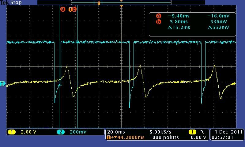
At like a cranking condition ~300rpm
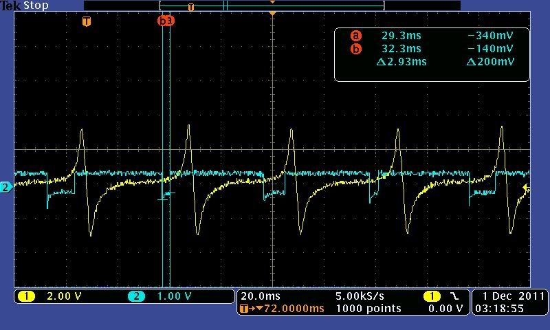
At a cruise like condition (not sure of rpm but it's up there)
So be sure to add that.The Hall input requires a 12 Volt pull up, so:
On a V3 main board: Install a 1K Ohm, 1/4 Watt resistor between the right side (non-banded) end of D1 and the left leg (banded end) of D9 and solder it in place. Use wires to extend the resistor leads, and wrap the resistor and connections (overlapping the wire insulation) with heat shrink tubing. Make sure the jumper cannot touch any other components. D1 is located above 2005 in the copyright notice. D9 is located near the voltage regulator (U5) on the left side of the heat sink.
On a V2.2 main board: Install a 1K Ohm, 1/4 Watt resistor between the right side (non-banded) end of D5 and the left leg (banded end) of D12 and solder it in place. Use wires to extend the resistor leads, and wrap the resistor and connections (overlapping the wire insulation) with heat shrink tubing. Make sure the jumper cannot touch any other components. D5 is located above www in the URL. D12 is located on the top left side of the PCB.