IGBT output voltage = ~540mV?

This forum is for discussing ignition setup, tuning, and troubleshooting for MS-II. Click these links for info on GM's HEI, EDIS, direct coil control, others.
Forum rules
Read the manual to see if your question is answered there before posting. Many users will not reply if the answer is already available in the manual.

If your question is about troubleshooting, configuration, or tuning, you MUST include your processor type (MS-I or MS-II) and code version in your post. If your question is about PCB assembly or modifications, you must also include the main board version number (1.01, 2.2 or 3.0). For tuning/troubleshooting questions, please attached a datalog and your MSQ file to your post.

If you have questions about MS1/Extra or MS2/Extra code configuration or tuning, please post them at www.msextra.com Such questions posted here will be moved to: a temporary MSextra sub-forum, where they will be removed after 7 days

The full forum rules are here: Forum Rules, be sure to read them all regularly.
Post Reply
Throttler
MegaSquirt Newbie
Posts: 9
Joined: Sun Dec 27, 2009 12:58 pm

IGBT output voltage = ~540mV?

Post by Throttler »

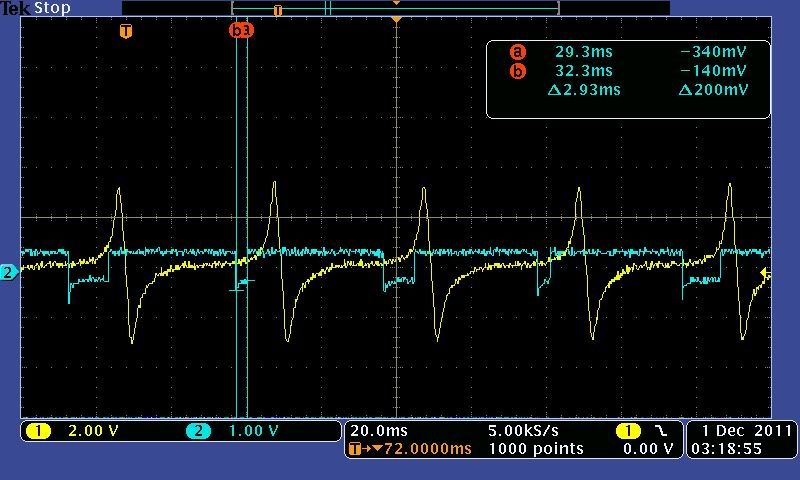
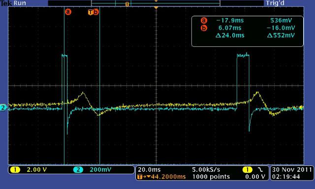
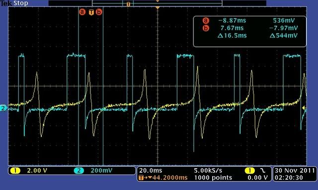
So after having some major trouble trying to use my stock Toyota igniter and a Bosch module to control my coil, I have decided to forget about the igniter/module and just use the MS direct coil control. So I was modifying my MS2 V3 board to install the jumpers per the megamanual, started bench testing with the Jimstim, o-scope, and distributor driven by a drill. Is it correct that the output of the Q16 IGBT is only like 540mV? Here are some oscope traces, and note that the scale of the yellow VR input and the blue IGBT output on IGBTOUT/IGN are different.

At like a cranking condition ~300rpm
Image

At a cruise like condition (not sure of rpm but it's up there)
Image
Bernard Fife
Master Squirter
Posts: 475
Joined: Thu Oct 29, 2009 12:54 pm

Re: IGBT output voltage = ~540mV?

Post by Bernard Fife »

Throttler,

The IGBT doesn't really have a 'voltage signal', instead it grounds an external device (or not). So if you want to send a voltage signal, you have to attach a 'pull-up circuit' This is a Voltage supply (5V or 12V depending on what your module wants) fed to the output through a curtrent limiting resistor (1K Ohms or so).

Then when the IGBT flow current, the output signal voltage goes low, and when the IGBT shuts off the current the output signal voltage goes high.

In the manual, on this page: http://www.megamanual.com/ms2/vast.htm it says:
The Hall input requires a 12 Volt pull up, so:

On a V3 main board: Install a 1K Ohm, 1/4 Watt resistor between the right side (non-banded) end of D1 and the left leg (banded end) of D9 and solder it in place. Use wires to extend the resistor leads, and wrap the resistor and connections (overlapping the wire insulation) with heat shrink tubing. Make sure the jumper cannot touch any other components. D1 is located above 2005 in the copyright notice. D9 is located near the voltage regulator (U5) on the left side of the heat sink.
On a V2.2 main board: Install a 1K Ohm, 1/4 Watt resistor between the right side (non-banded) end of D5 and the left leg (banded end) of D12 and solder it in place. Use wires to extend the resistor leads, and wrap the resistor and connections (overlapping the wire insulation) with heat shrink tubing. Make sure the jumper cannot touch any other components. D5 is located above www in the URL. D12 is located on the top left side of the PCB.
So be sure to add that.

Lance.
"Never wrestle with pigs. You both get dirty and the pig likes it.” - George Bernard Shaw
Throttler
MegaSquirt Newbie
Posts: 9
Joined: Sun Dec 27, 2009 12:58 pm

Re: IGBT output voltage = ~540mV?

Post by Throttler »

Lance,

First off I really appreciate the reply. I had a 5v pullup when I was trying to drive a signal to the stock Toyota igniter (which is an ESA system on this 92 Paseo) which was very similar but not exacly the same as on the VAST system you linked.

But my understanding from reading step 65 of the megamanual is you pretty much have 3 options:

1. Let the processor itself drive 5v, very low current (~milliamps) step signal to a device like HEI. This is achieved by jumpering JS10 to IGN

2. Use the IGBT in conjunction with a 5v or 12v pullup to drive current to an ignition module or igniter. This allows the signal to go high and low. The igniter/module ultimately controls the coil.

3. Use the IGBT to control the coil directly. I think I now understand that the voltage readings are okay from the IGBT circuit. The circuit for direct coil control is just providing a switched ground path from the primary coil, allowing it to charge for some small amount of time, then open, letting the magnetic field decay, and inducing a current in the secondary winding that forms the spark.

Since the IGBT is working on the negative side of the coil, I might have my settings in tunerstudio wrong, I think I need to invert the signal so it stays high, then goes low.
DonTZ125
Experienced Squirter
Posts: 337
Joined: Sat May 16, 2009 1:49 pm
Location: Scarborough, ON
Contact:

Re: IGBT output voltage = ~540mV?

Post by DonTZ125 »

I've read this first post about 4 times, trying to make sense of the waveform.

Throttler - if you are trying to drive the coil directly using nothing but the distributor to send spark to your various plugs, then Lance's first paragraph is correct - you connect the coil negative directly to the IGBOUT pin with nothing in between. Pull-up resistors will only confuse matters.

If you're looking for something to to test with and prove this circuit is working, then a little dash-lamp bulb hooked up to +12v at one end and the IGBT at the other should give the result you're after.
Bernard Fife
Master Squirter
Posts: 475
Joined: Thu Oct 29, 2009 12:54 pm

Re: IGBT output voltage = ~540mV?

Post by Bernard Fife »

Throttler,

Yes, as Don says, if you are controlling a coil directly from its negative terminal , then you don't need a pullup (unless you want to look at the signal temporarily, then you can use a pull-up - which is what Don's suggestion for a bulb is). You only need to pull-up if you are trying to send a voltage signal (such as to a VAST module).

For direct coil control, see: http://www.megamanual.com/ms2/vb921.htm. Don's suggestion of using a bulb to verify the 'Spark Output' setting is easy and fool-proof.

Lance.
"Never wrestle with pigs. You both get dirty and the pig likes it.” - George Bernard Shaw
Throttler
MegaSquirt Newbie
Posts: 9
Joined: Sun Dec 27, 2009 12:58 pm

Re: IGBT output voltage = ~540mV?

Post by Throttler »

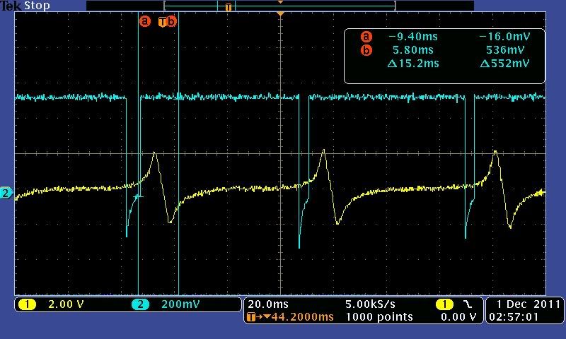
Lance, after re-reading your post, the first sentence is what I was looking for. My only concern now with this working is that making sure the o-scope traces are representative of a circuit that is switching between open and ground, since I think this is what the coil negative is going to need. I switched some settings in tunerstudio, and here is the waveform I think I'm going to go to the car with:

Cranking
Image

Idle
Image
Post Reply