1997 Chrysler Cirrus 2.5 wiring questions
Posted: Thu Apr 09, 2009 3:34 pm
I've got my head wrapped around most of the wiring for the megasquirt as I've done a ton of research before thinking about actually buying the unit (MS I v3 or maybe 2.2), but there are two things that I still can't quite understand. Well, since i'm only looking to control fuel for now, that only leaves one thing. This would be the tach/crank position input. I have a 1997 Chrysler Cirrus with the 2.5L Mitsubishi/Chrysler engine which is extremely similar to the 3.0 6g72 from the Eclipse.
However, the crank sensors differ. The one from the 2.5L is driven from reading little notches in the flexplate whereas the one from the 3.0L is driven off reading the crankshaft in the "front" of the engine. As I understand it, the 2.5L uses a hall effect sensor since it has "a metal shutter wheel, which has small evenly-spaced windows." Am I correct? Also, would the 3.0 use the VR sensor since it is reading the crank (i'm assuming the crank has magnets in it)?
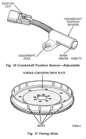
2.5 Crank Position Sensor and Flexplate
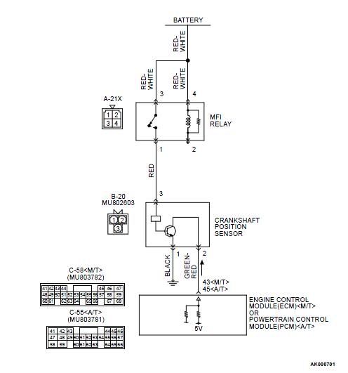
Well, regardless, both of these setups confused me by flipping back and forth between the FSMs and the megasquirt wiring diagram. The MS wiring diagram shows a + and a - for hooking up the tach/crank position input. However, for sake of simplicity let's just take the 2.5L, there's an 8v supply coming from the ecm, going to it (the crank sensor) and ending up at the distributor. Then it has a sensor ground and finally we have the crankshaft sensor signal going straight to the ECM. I'm guessing that the only two wires i'd need (considering that i'm only going to be running fuel) are the crankshaft sensor signal going to pin 24 and the sensor ground going to pin 2 on the MS? So, would I just let the ECM supply it with 8v or am I missing something here?
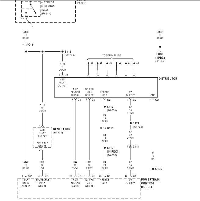
On the other hand, we have the 3.0L sensor. I'm not really going to need to run this, but just for reference i'd like to know how this would be wired in if I were to chose this route. It has a 12v wire going to a relay, a black going to ground, and 5v coming from the ECM. This seems much more different than the 2.5's. Is the 3.0's crank sensor getting a switched 12v source, going to a sensor ground, and sending 5v to the ECM? I'm not too sure how the sending of the signal is working. The wiring diagram makes it look like the ECM is sending the sensor the 5v, but then it's also getting 12v from the relay. Very confusing.
3.0 Crank Sensor wiring diagram
Well, I guess what i'm trying to ask, is how would I wire up the 2.5's crank input to the MS? I'm thinking of leaving the 8v wire as-is, splicing the sensor ground and sending it to the MS, and splicing the crankshaft sensor signal and sending that to the MS too. Might I be missing something here? Also, I saw that the 2.2v of the megasquirt I connects to the negative side of the coil instead of a crank sensor. Could I just grab the negative side of the coil (i'm guessing this is the dark green wire coming from the "generator/coil?") and wire it straight to pin 24 to achieve the same thing as the crank sensor?
Thanks in advance, I really appreciate it.
However, the crank sensors differ. The one from the 2.5L is driven from reading little notches in the flexplate whereas the one from the 3.0L is driven off reading the crankshaft in the "front" of the engine. As I understand it, the 2.5L uses a hall effect sensor since it has "a metal shutter wheel, which has small evenly-spaced windows." Am I correct? Also, would the 3.0 use the VR sensor since it is reading the crank (i'm assuming the crank has magnets in it)?
2.5 Crank Position Sensor and Flexplate
Well, regardless, both of these setups confused me by flipping back and forth between the FSMs and the megasquirt wiring diagram. The MS wiring diagram shows a + and a - for hooking up the tach/crank position input. However, for sake of simplicity let's just take the 2.5L, there's an 8v supply coming from the ecm, going to it (the crank sensor) and ending up at the distributor. Then it has a sensor ground and finally we have the crankshaft sensor signal going straight to the ECM. I'm guessing that the only two wires i'd need (considering that i'm only going to be running fuel) are the crankshaft sensor signal going to pin 24 and the sensor ground going to pin 2 on the MS? So, would I just let the ECM supply it with 8v or am I missing something here?
On the other hand, we have the 3.0L sensor. I'm not really going to need to run this, but just for reference i'd like to know how this would be wired in if I were to chose this route. It has a 12v wire going to a relay, a black going to ground, and 5v coming from the ECM. This seems much more different than the 2.5's. Is the 3.0's crank sensor getting a switched 12v source, going to a sensor ground, and sending 5v to the ECM? I'm not too sure how the sending of the signal is working. The wiring diagram makes it look like the ECM is sending the sensor the 5v, but then it's also getting 12v from the relay. Very confusing.
3.0 Crank Sensor wiring diagram
Well, I guess what i'm trying to ask, is how would I wire up the 2.5's crank input to the MS? I'm thinking of leaving the 8v wire as-is, splicing the sensor ground and sending it to the MS, and splicing the crankshaft sensor signal and sending that to the MS too. Might I be missing something here? Also, I saw that the 2.2v of the megasquirt I connects to the negative side of the coil instead of a crank sensor. Could I just grab the negative side of the coil (i'm guessing this is the dark green wire coming from the "generator/coil?") and wire it straight to pin 24 to achieve the same thing as the crank sensor?
Thanks in advance, I really appreciate it.