Enclosed Relay Box
Posted: Sun Oct 18, 2009 4:44 pm
Figured I should start a new topic on this, drifted quite a bit from the original waterproof D-sub connector topic in my earlier thread.
This one will focus on enclosing the relay box, and basically doing what I can towards making the relay board a bit more survivable in the elements.
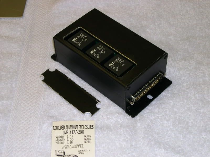
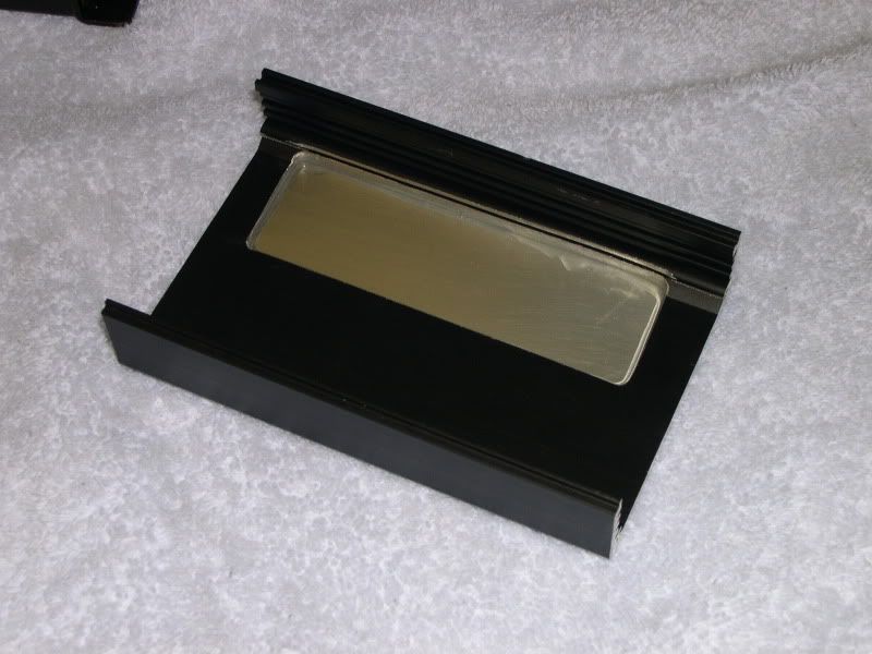
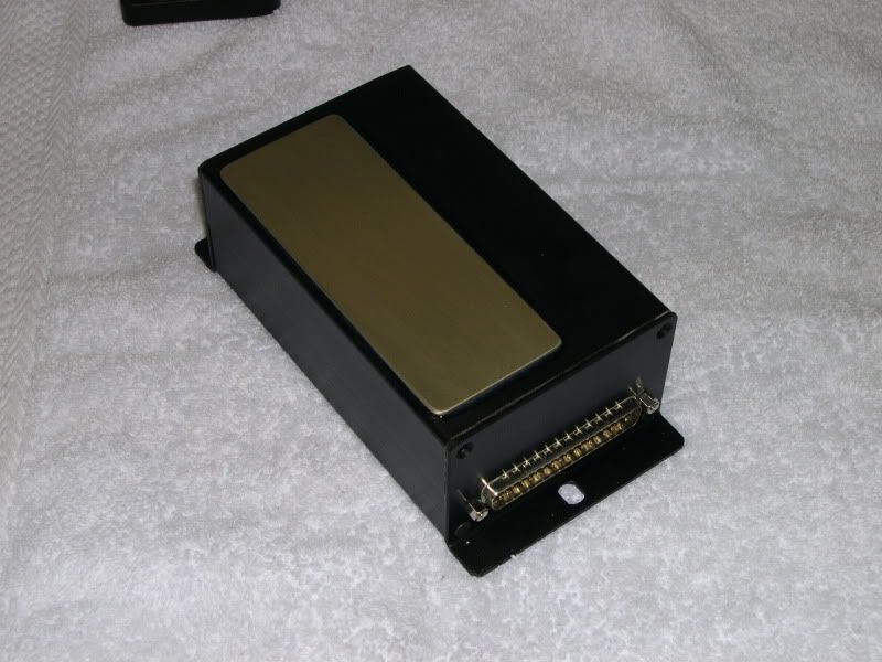
Picked up an LMB Heeger EAF 200 enclosure kit, basically the same as the 1/2 chassis supplied with the relay board kit, but with full top and bottom and end plates. Had to modify one endplate for the D-sub connector to pass through. Also cut a hole in the top as the relays stick up just a bit too high for it to fully close (exactly as Ollie said it would in the earlier thread). With the board in the bottom slot of the chassis, the relays sit up just barely higher than the interior surface of the top section, but do not protrude past the top when a clearance opening is cut out. This allowed fitting a simple flat aluminum plate on top to re-seal the opening. In this case I used 0.062" aluminum and epoxied it into place. I'll shoot the top with some satin black to clean up the appearance.
Next up will be cutting openings in the opposite endplate for the misc. wiring to pass through, using snug fitting rubber grommets to help seal it up. The manual recommends installing breathing holes in the chassis under the board to avoid condensation and corrosion issues. I guess I'll have to do that in top and bottom now, however I'd like to use some type of filter medium over the holes to keep out foreign materials. Have to see what I can come up with for this.
Anyway - the weekend's progress:
Assembled chassis with opening cut into the top (and cut-out section setting along side).
Top showing cut-out section from under-side (and plate epoxied on top).
Assembled relay board and enclosed chassis.
More to come.....
Jeff
This one will focus on enclosing the relay box, and basically doing what I can towards making the relay board a bit more survivable in the elements.
Picked up an LMB Heeger EAF 200 enclosure kit, basically the same as the 1/2 chassis supplied with the relay board kit, but with full top and bottom and end plates. Had to modify one endplate for the D-sub connector to pass through. Also cut a hole in the top as the relays stick up just a bit too high for it to fully close (exactly as Ollie said it would in the earlier thread). With the board in the bottom slot of the chassis, the relays sit up just barely higher than the interior surface of the top section, but do not protrude past the top when a clearance opening is cut out. This allowed fitting a simple flat aluminum plate on top to re-seal the opening. In this case I used 0.062" aluminum and epoxied it into place. I'll shoot the top with some satin black to clean up the appearance.
Next up will be cutting openings in the opposite endplate for the misc. wiring to pass through, using snug fitting rubber grommets to help seal it up. The manual recommends installing breathing holes in the chassis under the board to avoid condensation and corrosion issues. I guess I'll have to do that in top and bottom now, however I'd like to use some type of filter medium over the holes to keep out foreign materials. Have to see what I can come up with for this.
Anyway - the weekend's progress:
Assembled chassis with opening cut into the top (and cut-out section setting along side).
Top showing cut-out section from under-side (and plate epoxied on top).
Assembled relay board and enclosed chassis.
More to come.....
Jeff