Page 1 of 1
Coax Wire and CPS
Posted: Tue Jun 14, 2011 5:41 am
by skyy406
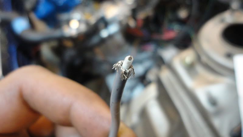
This might sound like a stupid question but I want to ask it anyway. On the MSII there is the Silver Coaxial wire that goes to the Crank position sensor. There is a wire like mesh around a white wire. I need to legnthen that wire. Is there any specific way to do this?
Also I have a CPS I bought from Boost engineering and a trigger wheel from DIYAutoTune. The CPS has a blue wire and a green wire. Does anyone know which wire is power and which wire is ground?
Re: Coax Wire and CPS
Posted: Tue Jun 21, 2011 5:24 am
by skyy406
Anyone??
Re: Coax Wire and CPS
Posted: Tue Jun 21, 2011 6:13 am
by 8974Ollie
You may have to lengthen the outer wire by cutting back the gray outer insulation, gather up the outer shield wire and twist into a pig tail and solder a length of regular wire to it.
Remember, only solder the shield to ground on the MegaSquirt end.
I would contact Boot Engineering to find out which wire is power and which is ground.
Re: Coax Wire and CPS
Posted: Tue Jun 21, 2011 6:26 am
by dc
Skyy
In my experience it is not recommended to splice coax, I would replace it with a longer wire. The FORD EDIS is a 2 wire pickup and even though it it has a wiring diagram you can still end up switching the 2 wires to get the correct polarity. I would hook up the wires and then if required switch them, I would replace that single coax for 2 wire shielded cable
http://www.DIYAutoTune.com/catalog/wire ... p-123.html this will help with any noise problems.
Re: Coax Wire and CPS
Posted: Tue Jun 21, 2011 8:30 am
by Matt Cramer
While splicing coax is a pain, I'd probably go about it in this manner if I had to do it.
1. Join inner wires together with a solder joint or uninsulated butt splice.
2. Cover the center wire joint with heat shrink tubing.
3. Pull the foil wraps / braids as close to each other as you can get them and solder. If necessary, use some stranded wire to extend them.
4. Cover with bigger heat shrink tubing.
Re: Coax Wire and CPS
Posted: Mon Jun 27, 2011 10:07 am
by skyy406
Matt,
That's pretty much what I did. I twisted a bunch of the braided wire and soldered that to some regular wire and heat shrinked the connection. I then stripped the inside wire and entended that and hear shrinked that wire. I then heatshrinked them both again, and wrapped the wires in electrical tape. Then wire loom, and wrapped that also in electrical tape.... never too careful

I would have purchased that 10' long extension but that wouldn't have been long enough still.
My only issue still is that I do not know which wire is power and ground on the sensor side. Again, the sensor has a green and a blue wire coming off of it.
Any help with that is appreciated.
Re: Coax Wire and CPS
Posted: Thu Jul 07, 2011 7:50 am
by skyy406
Hey all,
Im coming down to the wire here (pun intended)
I really need to know how I can discern which wire (green or blue) is the power/ground for this crank position sensor that I bought from
www.boostengineering.com
Please help.
Peter
Re: Coax Wire and CPS
Posted: Thu Jul 07, 2011 10:40 am
by convertables_10
you can use a volt meter and a trigger wheel to detirmine the polarity. Set your trigger wheel up steady and pass your sensor over it with the wires attached to your volt meter. I have had to check a few that way and have another to check soon.
Re: Coax Wire and CPS
Posted: Fri Jul 08, 2011 7:39 am
by skyy406
Hmmm
I guess I'll have to try that. It sure is a pain in the behind that boost engineering didn't tell me which was which- especially with their kits being as expensive as they are.