Good Day Matt,
Would you kindly advise me on this wiring issue, please for my MS 11 V3 board
Reference item No-52 in the construction sheets---- "Selecting the Tach Input circuit jumpers".
I am using a EDIS4 Ford timing system, so I use the Hall Optical Circuit
With regard to the 3rd., paragraph and the note to jumper " TSEL OPTOOUT". There are 2 solder wire locations near the "TSEL" printing on the board---and then a further 3 solder locations at right angles, which are marked "OPTOOUT.
Between where should I solder the jumper lead?"
My thanks for your help on a minor matter.
Regards Ian Cowen.
Tach. Input Circuit.
Forum rules
Read the manual to see if your question is answered there before posting. Many users will not reply if the answer is already available in the manual.
If your question is about troubleshooting, configuration, or tuning, you MUST include your processor type (MS-I or MS-II) and code version in your post. If your question is about PCB assembly or modifications, you must also include the main board version number (1.01, 2.2 or 3.0).
If you have questions about MS1/Extra or MS2/Extra code configuration or tuning, please post them at www.msextra.com Such questions posted here will be moved to: a temporary MSextra sub-forum, where they will be removed after 7 days
The full forum rules are here: Forum Rules, be sure to read them all regularly.
Re: Tach. Input Circuit.
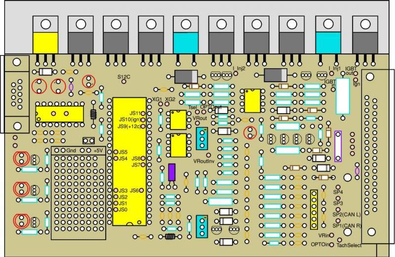
If you have fitted the surrounding components, there should only be three remaining choices in that area. The two nearest the power transistors are Tsel and OPTOout. The one beneath them is VR out. This might help:-
Dave P, London UK.
Rover V-8
MSII V3
EDIS
Tech Edge Wideband
Rover V-8
MSII V3
EDIS
Tech Edge Wideband