20v 4AGE w/MS2, VERY NEW, need lots of help...

For discussing how to choose sensors and create a wiring harness for all Bowling and Grippo versions of the MegaSquirt® EFI controller.
Forum rules
Read the manual to see if your question is answered there before posting. Many users will not reply if the answer is already available in the manual.

If your question is about troubleshooting, configuration, or tuning, you MUST include your processor type (MS-I or MS-II) and code version in your post. If your question is about PCB assembly or modifications, you must also include the main board version number (1.01, 2.2 or 3.0).

If you have questions about MS1/Extra or MS2/Extra code configuration or tuning, please post them at www.msextra.com Such questions posted here will be moved to: a temporary MSextra sub-forum, where they will be removed after 7 days

The full forum rules are here: Forum Rules, be sure to read them all regularly.
Post Reply
cds00bsmg
MegaSquirt Newbie
Posts: 1
Joined: Wed Sep 12, 2007 5:29 am

20v 4AGE w/MS2, VERY NEW, need lots of help...

Post by cds00bsmg »

Im trying to wire up a MS2 on a 20v 4AGE. I have not purchased the MS yet or any other components, just the engine itself which is on its way with no harness or ECU, but all sensors. I will be using a 12 foot MS Harness and wiring up to a pre-assembled MS, both from http://www.DIYAutoTune.com.

If anyone can help, please reply. Im looking for input from those who have done it, and documented their process by photo. So PLEASE post pictures of wiring up your harness, where sensors go, everything. I'd then like to try and make this a "HOT-TO" for here, and club-4ag, or any other sites where this is a common interest....

Please do not post links to msefi, megamanual, or other techno babble. The purpose of this topic is for someone who knows nothing about Megasquirt or whats needed, and how to install it sucessfully with no required speciality except for general soldering/splicing skills and a decent tool set. Please try to only cover the basics: Engine control, starting circuit, charging circuit. As nice as gauges, AC, PS, fan control, diagnosis connectors, stuff for emissions, etc... are nice... they are not required to get the car starting and driveable. If the OEM Toyota sensor does not work with MS, please refer to the GM sensor that needs to be adapted, and if possible always show accompanying pictures. Also if wiring something differs depending on what version MS you have please try and make it so that us dummies comprehend. Finally, if there are required capacitors or resistors, etc.. please try and make it as clear as possible what you are describing to do.

For the purpose of the easiest and most widely known sucess and compatibility, this will be regarding standard bank injection with stock high impedance injectors, and the use of the EDIS-4. (Please show pictures)

If you plan on explaining what to do on the stock distributor or high impedance injectors, (please be prepared to post accompanying pictures step, by step, and with a clear diagram or dont post at all.)

Lastly, THANK YOU SO MUCH IN ADVANCE.

Let's get started!
This is what Im working with:
Image


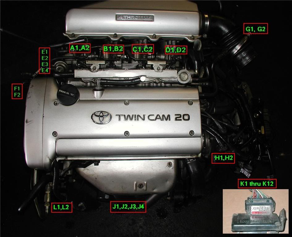
I've labelled most of the basic sensors needed with its general location, etc, here is the key:

A1: Injector Power
A2: Injector Ground
B1: Injector Power
B2: Injector Ground
C1: Injector Power
C2: Injector Ground
D1: Injector Power
D2: Injector Ground
E1: Throttle Position Sensor - Pin 1
E2: Throttle Position Sensor - Pin 2
E3: Throttle Position Sensor - Pin 3
E4: Throttle Position Sensor - Pin 4
F1: VVTI - Pin 1
F2: VVTI - Pin 2
G1: Intake Air Temp Sensor - Pin 1
G2: Intake Air Temp Sensor - Pin 2
H1: Coolant Temp - Pin 1
H2: Coolant Temp - Pin 2
J1: O2 Sensor - Wire 1
J2: O2 Sensor - Wire 2
J3: O2 Sensor - Wire 3
J4: O2 Sensor - Wire 4
K1-K12: EDIS Pin 1-12
L1: VR Sensor 1
L2: VR Sensor 2

Below is the pinout for the MS harness from DIY Autotune:

Please help mix and match. I do know how to use a DVOM know exactly how electrical circuits work (atleast OEM ones), resistors, volts, ohms, amps, rosin core soldering, etc... But I'd like to have this so simple that even if I didn't know how those things worked or how to do those, I could still follow this page and figure out how to wire up the MS. Thanks.


Just some guesses on some connectors:

A1: Pin 32
A2: Pin 33
B1: Pin 34
B2: Pin 35
C1: Pin 32
C2: Pin 33
D1: Pin 34
D2: Pin 35
E1: ?
E2: ?
E3: ?
E4: ?
F1: ?
F2: ?
G1: Pin 20
G2: Pin 17, 18, or 19
H1: Pin 21
H2: Pin 17, 18, or 19
J1: O2 warming - 12v (switched)
J2: O2 warming - Grounded
J3: O2 signal positive: Pin 23
J4: O2 signal ground: Grounded
K1: Pin 24
K2: ?
K3: Pin 36
K4: ?
K5: L1
K6: L2
K7: ?
K8: ?
K9: ?
K10: ?
K11: ?
K12: ?
L1: K5
L2: K6

Is any of this even close to correct?[/img]
rabiddeity
MegaSquirt Newbie
Posts: 5
Joined: Tue Mar 13, 2007 9:28 pm
Location: back in the USA

Post by rabiddeity »

If you want to rewrite the MS manuals for a specific car, that's cool... but we can't do it for you. In the end, you're going to need to read the manuals, figure out what you don't understand, and then ask here. That said, I'll try to clear up some things that appear to be a bit off with your initial diagram.

First off, if your setup didn't come with an ECU or associated relays, you'll probably need to build a relay box yourself, or buy one (many of the retailers sell a "relay board" kit specifically for this purpose).
http://www.megamanual.com/system.gif
So if you don't have a fuse/relay box, get one of these. It has screw terminals for all the sensors, everything is labeled, and it's pretty straightforward to hook up.

Injectors

MS activates the injectors by grounding them. If you were going to run the injectors full duty, you'd hook the injector ground wire to ground, and the injector power to a power lead (through the aforementioned fuses and relay).

Take a look at the diagram here: http://www.megamanual.com/v22manual/mwire.htm
We're gonna modify it slightly.

The ground wires from injectors 1 and 4 should go to pins 32 and 33 (MS injector bank 1), and the ground wires from injectors 2 and 3 should go to pins 34 and 35 (MS injector bank 2). 32 and 33 are connected internally, and 34 and 35 are as well. In case you're interested, the reasoning is here. And the power leads will go through some fuses and a relay. Megamanual shows the main relay, but perhaps it's safer to run it through the fuel pump relay if yours is beefy enough (fused appropriately), and the fuel pump relay's activation plus lead to the main relay instead of the ignition. That way the fuel pump and injectors won't run unless the main relay is on AND the MS says it's OK. It's your call. Make a schematic before you start wiring, use the appropriate gauge, and choose the right fuses for the wiring you're using.

Throttle position sensor

Your TPS has 4 pins. You need to measure with a multimeter as you turn the throttle. You will ground one of the pins, and hook two of the others to MS, and ignore the fourth one. Unfortunately, you'll have to figure out which ones for yourself. You're looking for the three pins A, B, and C, such that when you turn the throttle, the resistance between A and C stays the same, the resistance between A and B increases, and the resistance between B and C decreases. Hook A to ground, B to "TPS signal" (pin 22) and C to "+5V TPS reference" (pin 26).

Temp sensors

The two temperature sensors, you'll have to get temperature curves for. Check the factory service manuals, they should have a table of temperatures and resistances, at least 3 pairs. To connect them, one pin goes to ground and the other goes to the MS at the appropriate pin. You can hook the temperature sensors in either way, they don't have a polarity. (Pins 17 and 18 are NOT grounds.)

The rest

Ground everything to the same point with a single lug or bolt. If you can't squeeze them all into one fitting, use a terminal block and hook that to an engine bolt.

If your stock sensor is a narrowband, the O2 heater power should be switched through a fused relay, just as you have written. You're alright there. If it's a wideband stock sensor (rare, but they do exist) then you'll need extra hardware to control and read it.

You will want an idle air solenoid or something, or it's gonna be a bear to cold start.

VVT is tricky. You'll probably control that via an extra signal wire with a spare port set to activate above a certain RPM. I can't really help you further, because I don't know when the stock VVT system engages.

I don't know how the stock EDIS wiring is set up. Can someone else chip in?
Post Reply