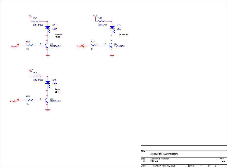
I messed up Q6
Read the manual to see if your question is answered there before posting. Many users will not reply if the answer is already available in the manual.
If your question is about troubleshooting, configuration, or tuning, you MUST include your processor type (MS-I or MS-II) and code version in your post. If your question is about PCB assembly or modifications, you must also include the main board version number (1.01, 2.2 or 3.0).
If you have questions about MS1/Extra or MS2/Extra code configuration or tuning, please post them at www.msextra.com Such questions posted here will be moved to: a temporary MSextra sub-forum, where they will be removed after 7 days
The full forum rules are here: Forum Rules, be sure to read them all regularly.
-
Art Vandelay
- MegaSquirt Newbie
- Posts: 6
- Joined: Thu Dec 07, 2006 7:19 am
- Location: Missouri
I messed up Q6
My question is, can I move on without this being remedied? I assume this part has something to do with the ignition LED, and I don't care if the LED works or not. The car is a Mustang SVO 2.3L and my initial set up will be MS3 (not X) with TFI ignition.
-
Bernard Fife
- Master Squirter
- Posts: 475
- Joined: Thu Oct 29, 2009 12:54 pm
Re: I messed up Q6
You can probably get away with a shorted Q6. R24 and R26 should prevent shorts to directly ground (but there could still be a constant draw on the power supply). If this was mine, I would:
- remove or cut one lead of R24 and/or D14 to prevent a possible short of VCC (the 5V power supply) to ground, AND
- remove or cut one lead of R26 to prevent shorting the processor's squirt-1 signal to ground.

This schematic is found here: http://www.megamanual.com/ms2/pcb.htm
Lance.