Single channel of injector driver failed

For discussing injector selection,manifold modifications, throttle bodies, fuel supply system design and construction, and FIdle valves and IACs.
Forum rules
Read the manual to see if your question is answered there before posting. Many users will not reply if the answer is already available in the manual.

If your question is about troubleshooting, configuration, or tuning, you MUST include your processor type (MS-I or MS-II) and code version in your post. If your question is about PCB assembly or modifications, you must also include the main board version number (1.01, 2.2 or 3.0).

If you have questions about MS1/Extra or MS2/Extra code configuration or tuning, please post them at www.msextra.com Such questions posted here will be moved to: a temporary MSextra sub-forum, where they will be removed after 7 days

The full forum rules are here: Forum Rules, be sure to read them all regularly.
Post Reply
Throttler
MegaSquirt Newbie
Posts: 9
Joined: Sun Dec 27, 2009 12:58 pm

Single channel of injector driver failed

Post by Throttler »

So one of my two injector drivers has failed, need to know how to test to see what component might have failed on the board.

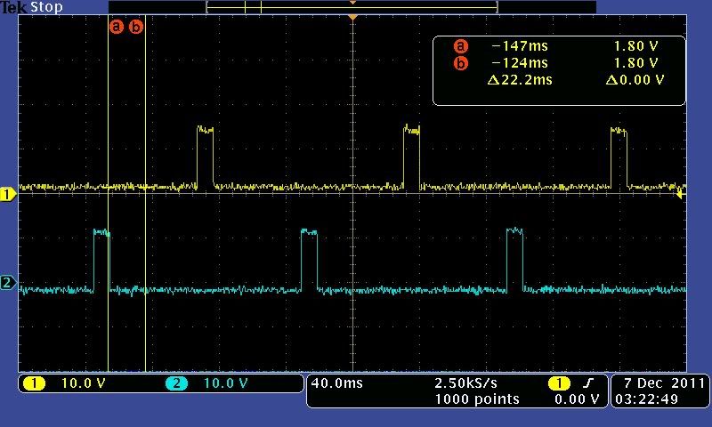
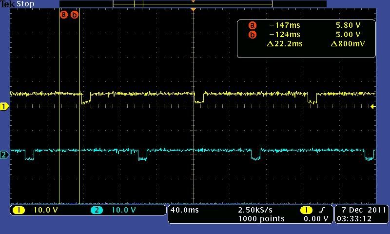
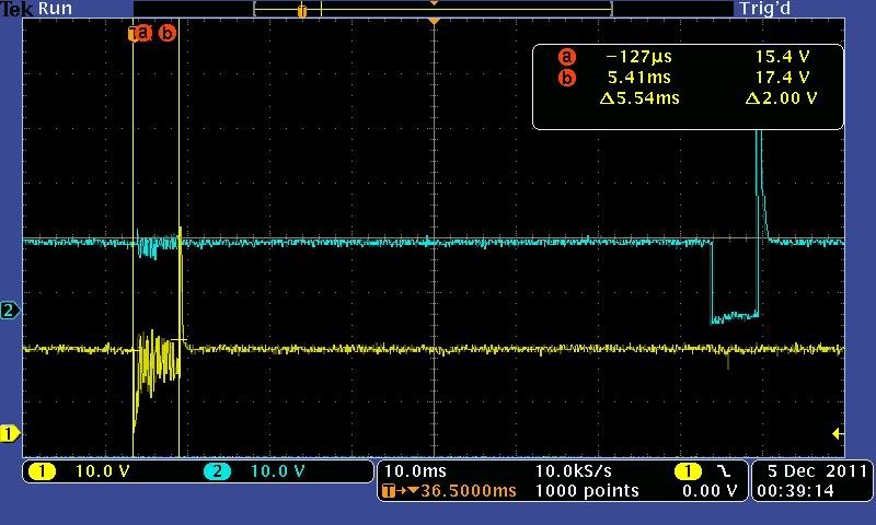
Original test, blue is injector driver for cylinders #2 (reading #2) & #4. Yellow is for #1 (reading #1) & #3, and clearly shows is bad.

Image

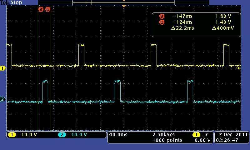
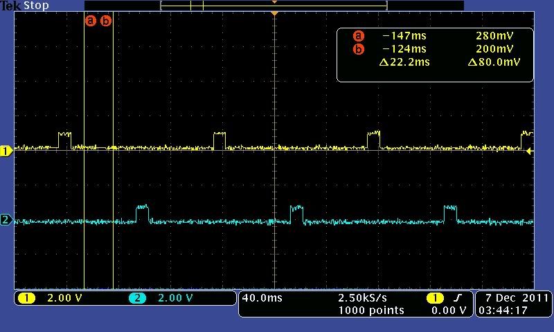
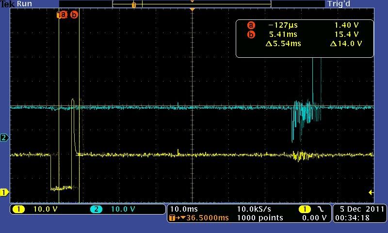
I swapped the injector driver for cylinders #1 & #2, keeping the measurement locations the same, and the problem swapped over to the #2 cylinder.

Image

I found this from another thread, is there anything else to check?
Matt Cramer wrote:Here is the injector driver circuit.

Image

The simplest test is if R15 is getting hot; this indicates a problem with the overcurrent protection feature.

Other than that, to test witout a Stim, you will need to probe the board with an oscilloscope at the following points:

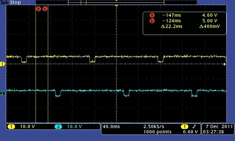
Processor pin 21. Should go from 5 volts high to ground when the injector fires.

Q1 pin 1. Goes from 0 to 12 volts when the injector fires.
Q1 pin 2. Goes from 12 volts to 0 when the injector fires. (Be sure to use an attenuator if your scope can't handle flyback spikes.)
Bernard Fife
Master Squirter
Posts: 475
Joined: Thu Oct 29, 2009 12:54 pm

Re: Single channel of injector driver failed

Post by Bernard Fife »

Doesn't anybody bother to look in the manual anymore? This isn't aimed at anyone in particular, just seems no one looks at what's been written in the manual, and instead checks only posts. Personally, I usually won't answer a question if the user hasn't checked the manual first: http://www.megamanual.com/mtabcon.htm

Throttler, see: http://www.megamanual.com/ms2/V3trouble.htm, step 11. There is a procedure there for checking the FET driver.

Lance.
"Never wrestle with pigs. You both get dirty and the pig likes it.” - George Bernard Shaw
Throttler
MegaSquirt Newbie
Posts: 9
Joined: Sun Dec 27, 2009 12:58 pm

Re: Single channel of injector driver failed

Post by Throttler »

Yeah, I'm sorry about that Lance, just there are about 1,847,783,371 locations to check in the MS documentation, and when you factor in all the differences in MS1, MS2, MS3, base B&G code, MS Extra, Megatune, Tunerstudio, then the differences in the cars it is very overwhelming. I word searched "injector" in the Troublshooting page, and I read the title of step 11 in the Troubleshooting section and said "I'm not having LED issues, I'm having injector driver issues" and discounted it.

I guess my plan (maybe Tuesday) is to scope the 2 injection circuits comparing the voltage waveform at each point b/w the good circuit and the bad circuit until I isolate the problem.

I think what caused it was when I was oscope probing the injector positive wire on the #1 cylinder, and I grounded the probe to the negative wire of the #1 injector. It blew a fuse in the fusebox. Then I stupidly replaced the fuse with the key still in "run" position, and that fuse promptly blew with a small blue arc from the fuse to the fuse recepticle. Then I realized something wasn't right and disconnected the oscope ground lead. Funny thing is, I could do that exact thing without problems on the stock ECM without the fuse blowing. Further, if I ground the oscope probe ground wire to ground (~engine block) it didn't seem to have an issue as far as I can tell (as I write this maybe I should re-check that assumption).
Throttler
MegaSquirt Newbie
Posts: 9
Joined: Sun Dec 27, 2009 12:58 pm

Re: Single channel of injector driver failed

Post by Throttler »

Okay I checked over the MS with the oscope tonite and I dont think I could find any smoking guns. I basically probed the 2 injection circuits at the corresponding components and compared the waveforms. I went about this in a semi-random manner, selecting components that were easily probed on the board. Even the output on the stim looked good, so maybe its in the jumper harness or engine harness (hope not). If there is anything else I should check please let me know.

R15 & R20
Image

Q1 & Q5 leftmost pin
Image

Q1 & Q5 center pin
Image

Q1 & Q5 rightmost pin was zero (IIRC)

Q12 & Q9 was solid 12v (i think) on all pins

D7 & D5
Image

R32 & R36 right lead
Image

R32 & R36 left lead
Image

INJ1 & INJ2 on stim screw headers
Image
Matt Cramer
Super Squirter
Posts: 2951
Joined: Sat Jul 03, 2004 11:35 am

Re: Single channel of injector driver failed

Post by Matt Cramer »

My guess is a broken FET in this case.
Throttler
MegaSquirt Newbie
Posts: 9
Joined: Sun Dec 27, 2009 12:58 pm

Re: Single channel of injector driver failed

Post by Throttler »

I put this thing back on the car to further try to diagnose it and it started and worked fine...for about an hour of run time or so, then started to do the exact same thing, AFR's on the gauge went way lean, then it died out, pretty sure the injector circuit went bye-bye again...so I'm thinking this is a thermal issue.

My Q1 and Q5 seem kind of 'loose' where the wires enter the black body. Also they don't really touch the heat sink all that well. Is this an issue?
Throttler
MegaSquirt Newbie
Posts: 9
Joined: Sun Dec 27, 2009 12:58 pm

Re: Single channel of injector driver failed

Post by Throttler »

Or I might have a cold solder joint on those connections...
trakkies
Super Squirter
Posts: 1162
Joined: Tue Dec 30, 2008 3:06 am
Location: SW London, UK

Re: Single channel of injector driver failed

Post by trakkies »

Throttler wrote:I put this thing back on the car to further try to diagnose it and it started and worked fine...for about an hour of run time or so, then started to do the exact same thing, AFR's on the gauge went way lean, then it died out, pretty sure the injector circuit went bye-bye again...so I'm thinking this is a thermal issue.

My Q1 and Q5 seem kind of 'loose' where the wires enter the black body. Also they don't really touch the heat sink all that well. Is this an issue?
They should be a tight fit to the heat-sink. The reason for it is to conduct heat from the device, and that depends on area in contact. It's possible some form of thermal runaway is interfering with their operation.
Dave P, London UK.
Rover V-8
MSII V3
EDIS
Tech Edge Wideband
Throttler
MegaSquirt Newbie
Posts: 9
Joined: Sun Dec 27, 2009 12:58 pm

Re: Single channel of injector driver failed

Post by Throttler »

I think I had some sort of cold solder joint on Q1 & Q5. Reflowed the solder and it's much more stable, and making better contact w/ the heat sink. Still kinda surprised these don't have a screw down to the heat sink like the others.
trakkies
Super Squirter
Posts: 1162
Joined: Tue Dec 30, 2008 3:06 am
Location: SW London, UK

Re: Single channel of injector driver failed

Post by trakkies »

Throttler wrote:I think I had some sort of cold solder joint on Q1 & Q5. Reflowed the solder and it's much more stable, and making better contact w/ the heat sink. Still kinda surprised these don't have a screw down to the heat sink like the others.
Not seen those - all I've come across are normal TO220 style. Are they self adhesive pads like the resistors? Although even those can be bought in TO220.
Dave P, London UK.
Rover V-8
MSII V3
EDIS
Tech Edge Wideband
Post Reply