Tach. Input Circuit.
Posted: Tue May 27, 2014 8:30 pm
Good Day Matt,
Would you kindly advise me on this wiring issue, please for my MS 11 V3 board
Reference item No-52 in the construction sheets---- "Selecting the Tach Input circuit jumpers".
I am using a EDIS4 Ford timing system, so I use the Hall Optical Circuit
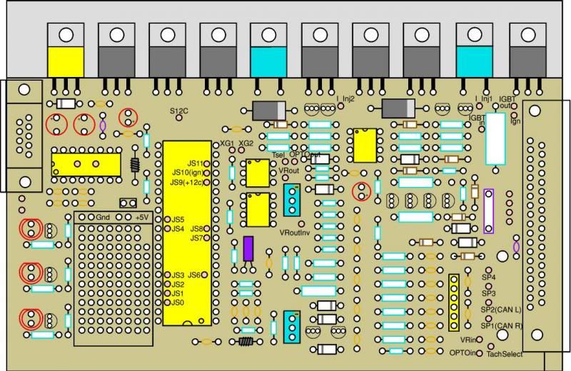
With regard to the 3rd., paragraph and the note to jumper " TSEL OPTOOUT". There are 2 solder wire locations near the "TSEL" printing on the board---and then a further 3 solder locations at right angles, which are marked "OPTOOUT.
Between where should I solder the jumper lead?"
My thanks for your help on a minor matter.
Regards Ian Cowen.
Would you kindly advise me on this wiring issue, please for my MS 11 V3 board
Reference item No-52 in the construction sheets---- "Selecting the Tach Input circuit jumpers".
I am using a EDIS4 Ford timing system, so I use the Hall Optical Circuit
With regard to the 3rd., paragraph and the note to jumper " TSEL OPTOOUT". There are 2 solder wire locations near the "TSEL" printing on the board---and then a further 3 solder locations at right angles, which are marked "OPTOOUT.
Between where should I solder the jumper lead?"
My thanks for your help on a minor matter.
Regards Ian Cowen.